REUSABLE WORKSHEETS
Scriptable Components - MathCAD Controls
MathCAD scriptable components take on a number of forms, but can be classified as:
1) Application Components,
2) Data Components and
3) Control Components.
As taken from the MathCAD help page regarding scriptable components:
"Although Mathcad has several application-specific components, you can exchange data between a Mathcad worksheet and any other application, as long as that application supports OLE Automation. The Scriptable Object component allows you to control any OLE application, including Mathcad, installed on your workstation. Before using the Scriptable Object component, you should be proficient in a supported scripting language and understand how the other application has implemented OLE."
The 'components' referred to in the first line are application components such as Excel. We learned how to use that last week. However, this is not a scriptable component. As in the description above, by MathSoft, such a component allows one to interface with other installed applications supporting OLE Automation. However, the ability to do so requires one to be proficient with a scripting language such as JScript or VBScript. Most scripting languages today are object-oriented, or at least based upon the concept. Although a simple concept to understand, it takes significant time and effort to become proficient in the application of scripting such that one is capable of communicating with and controlling an installed OLE application. As such, we will not discuss scriptable applications or data components.
However, scriptable controls are worth understanding. Although unnecessary to make a worksheet function properly, scriptable controls can help provide for a great looking, efficient and intuitive interface. In this worksheet, we will investigate the use of radio buttons, pushbuttons, slider controls, and textboxes. Also available are checkboxes and listboxes. Although not specifically discussed, they are rather intuitive and handled quite similarly as with the above controls.
A QUICK PRIMER ON SCRIPTED CONTROLS
Before we look at an example, It is important we understand some details of scriptable controls. Most of these elements will work out-of-the-box without modifying the underlying script. Each element is considered an object. Each object has a number of features known as properties, methods, and events. A property defines some attribute of the object such as its value, its color, or its state (on/off, etc.). Different objects have different properties. A method is a term defining a function or a procedure attached to that object. Common methods are Input( ) and Output( ). To reference a property or method of an object, we simply state the name of the object followed by the method or property delimited by a decimal point. An event is some action, such a mouse click, that invokes a method.
Although some object properties can be set programmatically, they are most easily set through the properties dialogue box. You can access the dialogue by right clicking on the object and selecting 'MathCAD Control Object > Properties. Most of the listed properties are aesthetic in nature, but there are some that MUST be properly set. For example:
-
Caption Available for checkboxes, radio buttons and push buttons. This is the visual label seen by the user. Although the component will function properly if you don't change it, you should do so to provide a descriptive label for the user.
-
-
Group ID Available for radio buttons only. Radio buttons are placed in groups to allow for a unique selection from within the group. As such, this property MUST be set.
-
-
Button ID Available for radio buttons only. The button ID uniquely identifies a button within a group.
-
-
Minimum/Maximum Slider only. Establishes the minimum and maximum output corresponding to slider position. Values between minimum and maximum are interpreted linearly.
-
-
Scrollbars Listbox only. Does not affect the functionality of the list box. However, if your selection items do not fit into the box as you've sized it, you may wish to show the horizontal and/or vertical scrollbars so the user is aware of additional items.
Each object also has an underlying script. It is within the script that methods are invoked. An example of a method that must be modified by the user is the AddString( ) method. This method is available only for listboxes and is how the user to defines the listbox items available to the user. Two other important methods used by all control items is Inputsx( ) and Outputsx( ) where the letter 'x' takes on the value of zero (0) through three (3). Each component can have a maximum of four inputs and four outputs. A common property associated with these methods is Value. As implied, this property represents the value of the method and object to which value is associated. For example, suppose you pass the number 56 to a single input of a pushbutton. The script associated to the pushbutton assigns this number to a local variable called 'mynumber' Further assume the script evaluates this input value and returns the number 156 and assigns it to a local variable 'yournumber'. We desire to pass this number to the single output of the pushbutton. Within the script itself, this is written programmatically as:
-
mynumber = PushBtn.Inputs(0).value
-
.
-
mynumber = foobar
-
blah blah
-
yournumber = foobar
-
.
-
PushBtn.Outputs(0).value = yournumber
Another method worth discussing is recalculate( ). Quite simply, this method recalculates the control. It may be invoked manually or may be automatically invoked by certain events. For example, the slider control has an event 'ValueChanged'. This event fires any time the slider position is changed. When the Slider.ValueChanged event fires, the recalulate( ) method is invoked and the slider control is recalculated.
The default script for each control component is invoked through any number of EVENTS. An event is some occurance causing an action to occur in accordance with the programmed script. For example, selecting a radio button may be detected as a 'click' event and force some preprogrammed calculation to occure. (other than the default passing of the button ID to the button output). Current events include but are not limited to:
-
Start Event fires automatically when a computation is started.
-
Exec Event fires when MathCAD supplies input or requests output from the control
-
Stop Event fires ONLY after a Start event fires AND the computation is complete
-
Click Event fires on a mouse click
-
DblClick Event fires on a mouse doubleclick
-
Error Event fires on an error
-
KeyDown Events fire in sequence when a key is pressed and released.
-
KeyPress
-
KeyUp
-
MouseDown Event fires when a mouse button is pressed
-
MouseMove Event fires when mouse cursor is passed over control component
-
MouseUp Event fires when a depressed mouse button is released
-
ReadyStateChange Event fires when a control transitions to the next ready state due to the amount of data received
-
SelectionChange Event fires when there is a change in Radio Button Group or Listbox Selection
-
ValueChanged Event fires when the a slider is moved
In the general case, we will likely be concerned only with the first three and the last three events. You may wish to review MathCAD's pages for more information. Using the 'search' function, enter 'button class' and press 'GO'. From the resulting list, select 'MathSoft Control Button Classes.
The example problem used to illustrate these components is the static analysis of a square threaded screw. The worksheet includes user-friendly elements for data input, selection choices to determine what result the analysis is to return, and a display element providing an English-like response to the solution of the problem. Let's see how this is done.
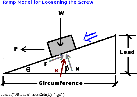
A particular problem in Statics is the solution of a square threaded screw. The basic solution process is to unwrap the threads and lay it out as an inclined plane. In the graphics below:
W = tensile or compressive force on the screw
P = Force applied tangent to the screw to cause screw to tighten/loosen
F = Force of friction
N = Normal force
R = Vector resultant of F and N
= Friction angle
= angle of threads
Pitch = distance between adjacent threads
Lead = distance between threads on the same spiral if screw is multi-threaded
Circumference based on mean screw diameter, not the nominal diameter
There are several computational conditions existing for such an analysis depending upon what one is trying to do. To allow for maximum flexibility, these conditions are listed below in a text region with corresponding radio buttons set to the side. Take some time to review the properties, the control object properties, and the script. You may also want to right click and select 'Show Arguments' to see the name of the variable assigned to each radio button. The assigned variable is 'cond'.
In the properties dialogue, (right click > Properties...), note the object name. This name is used within the script to refer to this object. If you change this name, you must also manually change the object reference in the script. For our purposes, it is alright to have all similar objects with the same name since the name is only used locally within the component script. However, if you were to use an external script to manipulate this worksheet, each element MUST be assigned a unique name.
Now right click and select 'MathSoft Control Object' > Properties. Note the entries for 'Caption', 'Group ID', and 'Button ID' in the resulting dialogue. The 'Button ID' must be unique for each button as this number is passed to variable 'cond' for use in the rest of the worksheet.
Finally, right click and select 'Edit Script'. The script is unchanged from default. Under the exec subroutine, note the line:
Outputs(0).Value = RadioBtn.SelectedButton()
This is the line that passes the ButtonID number to variable 'cond' through the single output, Ouputs(0).
Select one of the following Conditions (Condition 1 is Default)
Known => diameter, pitch & lead, applied torque (ie:Force P is known), coefficient of friction
Find => screw tension/compression (w) (Default)
Known => diameter, pitch & lead, screw tension/compression, coefficient of friction
Find => necessary torque (find Force P then translate to torque)
Known => diameter, pitch & lead, screw tension/compression, applied torque
Find => coefficient of friction (and self-locking coefficient of friction)
Known => diameter, screw tension/compression, applied torque, coefficient of friction
Find => pitch and lead


The above elements provide an attractive and intuitive user interface for data input. It consists of three different components for input, sliders, push buttons, and radio buttons (configured to look like push buttons). The text boxes are used to provide immediate feedback of the selected values. The tricky part of setting up controls of this nature is to be able to provide an output range for the sliders that make sense for the problem at hand, while still allowing for appropriate resolution to allow the user to select a desired value.
SLIDERS
The sliders for 'Pitch', 'Diameter', and 'm' are fairly easy to establish. First, go to the Control Object > Object dialogue box. Select a minimum and maximum value for the slider. In the present case, the values of zero and 100 are appropriate. Remember that the output of a slider is linear between the minimum and maximum values. Also, these numbers must be integers. However, we wish to limit the range of pitch from 0 to 0.5 inches, the range of diameters from 0 to 2 inches, and the value of 'm' from 0 to 0.5. To do so, we must modify the script. Right click and select 'Edit Script'. Locate the execute subroutine (this should be the subroutine within the script). Locate the line:
Outputs(0).Value = Slider.Position
Modify this line as follows:
Outputs(0).Value = Slider.Position*factor
where factor is some multiplyer used for achieving the output you desire. Since 'pitch' and 'm' are both limited numerically to 0.5, 'factor' is 0.005. Why not set the minimum and maximum from 0 to 1 with a factor of 0.5? Try it and see what happens. The reason the minimum and maximum values of the slider are integer values is because the difference dictates how many steps thre are between minimum and maximum. In other words, the resolution of the slider. So why not set minimum and maximum from 0 to 1000 with a factor of 0.0005? Again, try it and see. In this case, we could do this, but the resolution is to fine, making it difficult to accurately select a value. Also, note the numeric value is now to four decimal places. Debatably, we do not need this degree of accuracy for these values. However, if you do, these values are fine. On the other hand, one can play with the slider range and the multiplyer to achieve a desired result.
The sliders providing loading and torque input are a bit more complex. The reason is because we have allowed bolt diameters ranging from 0.02 to 2.0 inches. If one were to investigate the magnitude of the load a bolt can take in tension (or compression) over this range of diameters, one would see a range with orders of magnitude from 101 to 105. To handle this kind of range with a linear slide is difficult at best. Actually, a logarithmic slide would work well here, but does not exist. If you open up the script attached to the slide governing bolt loading, you will see a series of formulas based upon used to calculate an output based upon slider position. Where did these formulas come from?
Basically, I made a decision as to what ranges I wanted as output. The ranges were 0 to 100 in increments of 10, 100 to 1000 in increments of 100, etc, with the last range being 100,000 to 500,000 in increments of 100,000. These ranges were assigned to the range of the linear slide from 1 to 41. I then used MathCAD's regress( ) function to determine the set of equations necessary to do so. Double click on the reference below to the MathCAD worksheet used to do this.
Once the equations were determined, they were entered into the script in the order shown. Study this conditional structure. Note I did not use an 'Else' statement. The reason is directly related to the order in which the conditonals are presented. Since each conditional is a standalone statement, each is evaluated in turn. The last statement for which the condition holds true dictates the output of the script. If the order of the statements were reversed, this script would not work as designed.
Originally, the slider was set to a range of 1 to 41, the range for which the equations were regressed. It became apparent rather quickly the resolution of the output was not acceptable. To correct this, the slider range of the slider was modified to 1 to 4100. This provided 4099 steps. However, since the equations were regressed based upon a dependent variable ranging from 1 to 41, the value of the slider position had to be divided by 100. The resulting value was passed to the set of conditionals shown. The result was an output value to three significant digits. I eventually modified the range to 0 to 4600 to allow for a minimum output of zero and a maximum output of 1,000,000.
The slider used to provide an input for the value of torque was treated in much the same way. In fact, I used essentially the same equations, but changed the slider range to 0 to 370 with a minor modification to the equations (via a multiplier) to get the desired output value for torque.
Radio Buttons
Radio buttons are used to allow the user to select whether the screw is single, double or triple threaded. But these are push buttons you say? Actually, they are radio buttons configured to look like push buttons. Display the MathSoft Object Properties dialogue to view these settings. While you are there, note the values of GroupID and ButtonID. Since the radio buttons used to select the screw condition to be calculated was labeled group number one, we must provide a different group number, in this case, group two. As before, each button is assigned a unique ButtonID within the group and a unique caption so the user knows what the button is for. The ButtonID is passed to variable 'num' indicating a single, double or triple threaded screw. Inspection of the script will show no changes. The default script works just fine. One final observation, right click and select properties. The resulting dialoque indicates an object name of RadioBtn. As mentioned above, this is not a problem in our case even though the name is used multiple times. The only reason this is true is because we do not have an external script trying to manipulate this worksheet. If an external script is written to do so, each object must have a unique name so the script knows which object with you wish to work.
Push Button
The push button is used to indicate whether the analysis is based upon tightening the screw or loosening the screw. A push button, by its very nature, is a binary object. By default, the 'state' of the button, a button property, is either 'True' or 'False'. You may recognize this as Boolean outpput, and as such, the value of the output is either a zero (0) or a one (1). We could write a script to output a different pair of values, but it is still binary. That is, it will output only one of two values. An exception to this is if we write a script that generates a random number with each mouse click, but this is a unique situation.
Since the output is boolean, we can assign that value to a MathCAD variable to indicate whether or not we are tightening the screw or loosening the screw. The unique feature of this push button is the fact the caption changes with each mouse click to indicate whether we are tightening or loosening. Open the script. Note the programming that allows this to happen.
Sub PushBtn_Click()
If state = 0 Then
state = 1
PushBtn.Text = "Tighten Screw"
Else
state = 0
PushBtn.Text = "Loosen Screw"
End If
PushBtn.Recalculate()
End Sub
This subroutine is invoked upon a mouse click event. A conditional is used to sheck the state of the pushbutton. Note the conditional resets the state of the button upon each click and changes the text by reassigning an appropriate value to the PushBtn.Text property.
TextBoxes
The textbox elements are used only to display information. It should be noted the textbox only displays strings, it cannot display a number (unless converted to a string). Each textbox, as inserted in this sheet, has a single input and no outputs. Let's study the textbox used to display the coefficient of static friction, 'm', to review how these elements are setup. First, these elements are inserted into the worksheet with no inputs and a single output. So upon initial insertion, you will need to right click the element and click on 'Remove Output Variable', then repeat and click on 'Add Input Variable'. The next step is to specify the input variable. As with all placeholders in MathCAD, this placeholder can accept a formula. We wish to display the value of 'm'. However, 'm' is a number, so we must first convert it to a string. We can do so with the MathCAD string function num2str( ). Thus the input to the text box is 'num2str(m)'. This value is provided to the script through Inputs(0). Now we must modify the script.
Since the default textbox is inserted with an output and no inputs, the default script follows suit. The execution subroutine includes the line:
Outputs(0).Value = TextBox.Text
This must be changed to the following:
TextBox.Text = Inputs(0).Value
This statement assignes the Value of the string on Input(0) as the text string displayed by the textbox. If we left it as such, the text box would only a string representation of a number. We can use string concatenation to display a more descriptive string. Change the above statement to:
TextBox.Text = "u = " + Inputs(0).Value
This statement concatenates the string found on Inputs(0) to 'u = ' for a more meaningful display representing the coefficient of friction. The other textbooxes are scripted in a similar fashion.
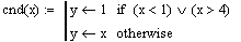
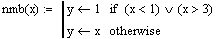
These statements provide default values for the variables 'cond' and 'num'. When this sheet is initially loaded, these varaiables have a value of zero. Due to how we setup our radio buttons, zero is not an acceptable value. Of course, if the user physically selects the condition desired for calculation and the type of screw, this is not an issue. But we want to ensure these input values are reasonable. By establishing arbitary functions, we can write a conditional that ensures each variable has an acceptable value that will not cause the worksheet to crash.

This graphic is purely aesthetic, but does provide an explanatory graphic showing how the screw is modeled. Since the analysis can be done on a screw as it is either tightened or loosened, there should be two graphics. But instead of inserting two different graphics and their associated overhead, we used a string concatenation to select one of two graphics we wish to display. The graphics we wish to display have filenames of friction0.gif and friction1.gif.
Right click the graphic and select show arguments. The input argument is actually a string function. The value received from the Tighten/Loosen push button is either a zero or a one. This number is converted to a string value to allow concatenation. Using the concatenate function, we construct a file name with the form './friction0.gif'. The two initial characters, './' tell MathCAD to look in the same directory as this worksheet. The rest of the function should be self-explanatory. If not, refer to last week's lecture on string functions.
Click the Tighten/Loosen push button above to see what happens.
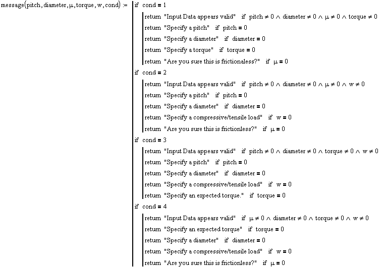
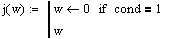
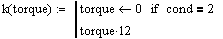
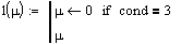
The message function below checks user input to ensure the user has specified proper input for the calculation selected. For example, 'Condition 1' finds the tensile/compressive load on the screw when given a screw pitch, diameter, applied torque, and a friction coefficient. If any of these values are zero, this routine provides a message to the user advising the user a particular value needs to be specified. The remaining functions, 'j', 'k', 'l', and 'o' sets the value being calculated to zero (ie: initializes the value).


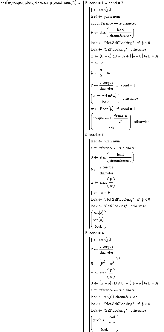
If you expand the area named 'Calculations', you will be able to view the program written to solve this problem. Since these calculations do not introduce any new elements or techniques, it is left for you to review at your convenience. Also, you must understand the solution of square threaded screws to understand this program. If you do not, you can skip the review of this program. It is not important for the understanding of the use of scriptable control objects. If you do review the program, but do not understand some programmatic element of the program, review the appropriate lecture material. If that still does not answer your question, contact your instructor.
cond 1 > Given diameter, pitch, torque, friction
Find: 1) friction angle
2) lead
4) circumference
5) thread angle
6) determine if self-locking
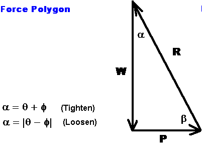
6) angles of force polygon
7) find P
8) find w
cond 2 > Given diameter, pitch, friction, w
Find: 1) friction angle
2) lead
3) circumference
4) thread angle
5) determine if self locking
6) angles of force polygon
7) find P
8) find Torque
cond 3 > Given diameter, pitch, torque, w
Find: 1) lead
2) circumference
3) thread angle
4) Find P
5) Find R from P & w
6) Find angles alpha and beta
7) Find friction angle (tightening vs. loosening)
8) If friction angle (8) is greater than friction angle (4)
return this friction angle
9) If friction angle (8) is less than friction angle (4)
set friction angle to friction angle (4)
10) Find w for stated torque and display
11) Find torque for stated w and display
12) u for self-locking equals thread angle
cond 4 > Given diameter, torque, friction, w
Find: 1) find friction angle
2) find P
3) find R from P and w
4) find alpha and beta
5) find thread angle from alpha and friction angle
6) find circumference
7) find lead
8) find pitch
Conspicuous in its absence is the use of any units during program calculation/execution. However, as implied by the display of input data in the textboxes above, units were, in fact, assumed. It is important to note that since we did not allow MathCAD to handle units for us, we must, as programmers, ensure all input is dimensionally valid. Although this was not explicitly stated above, all input elements were carefully crafted to ensure the numbers generated represented proper units as desired.
The function below named 'display', prepares the final solution for display to the user. Upon inspection, you can see all solutions are converted to strings with appropriate units 'tacked on'. The arguments of this function are 'cond', the variable provided by the radio buttons and indicating the type of calculation desired by the user, and 'data'. The argument 'data' is actually a variable to which is assigned the solution to the problem.


The message to the right are acutally displayed in textboxes. The textboxes are configured without borders. Both are setup in a very similar fashion to the textboxes at the start of this worksheet. Study the script and properties dialogues to see if you can determine how these messages are received from the functions above and how they are displayed with the differing fonts and font styles.